BMW ICOM Software Version : V2020.05
ISTA – D: 4.22.32,with SDP Programming Database 4.22.32
ISTA – P: 3.67.1.006 with Engineer Programming,supports the programming of BMW motorcycles and electric vehicles
can program F/G/I/K chassis for car (through the ICOM, not other cable )
Vin: V2020.2.15
BMW ETK: 2020.1
BMW KSD: 2020.01 Multilanguage
BMW FSC Navigation Code Generator
BMWAiCoder for BMW Coding
BMW ICOM A2 +B+C NEXT V2020.05, With free Software:
- Get engineer version, INPA 5.00,winkfp 5.2.3,NCS 3.5.1, e-sys 3.30,data V67.0. get Chinese software DR.GINI B020
- get count code navigation tool software FSC operator code
- get one-clik hidden brush tool BMWAi V4.6
- Add DIS Software for Old cars, DISV57 and DISV44,diagnosis and programming for BMW virtual machines.
A BMW E70 X5 2011 with 4300km,the owner described that when starting after parking,the EMF warning light on,and parking brake function can not work correctly.
Mechanic staff released the parking brake mechanically,and then use ISID to diagnosed,got the below fault code:
5F12 DSC: Brake-pad wear, front axle, brake pads
5F10 DSC: Brake-pad wear, front axle, sensor
6DDC DSC: EMF: interface
600E EMF: Control module: internal fault (engine circuit)
6011 EMF: Control module: internal fault (engine circuit)
6031 EMF: Emergency release detected
The E70 is equipped with electro-mechanical parking brakes (EMF) in batches, which are used to prevent stationary vehicles from moving on their own.The parking brake is operated by the parking brake button in the center console. The parking brake button is located in the center console, behind the gear selection button (GWS).
The parking brake button is simulated in the hand brake operating logic:
Pull up the parking brake button: the parking brake is activated
Press the parking brake button downward: the parking brake will quit working
The dynamic stability control system (DSC) is the main control unit of the electro-mechanical parking brake (EMF).When the engine running or the vehicle on road: The parking brake hydraulically acts on the disc brakes on the front and rear axles via DSC.When the engine is off and the vehicle is stationary: The parking brake is applied to the drum brake of the rear axle by means of an electro-mechanical servo unit.The release action can be triggered by pressing the parking brake button,and the correspondingly activated brake system opens.When stationary, the parking brake can only be released by manipulating the foot brake, whether the engine is running or off.
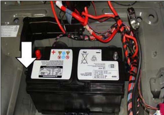
EMF powered by rear distributor (2 bus terminals KI.30),it can be adjusted electromechanically through the transmission mechanism connected to the motor and flange.At this time, the pull wires act on an expansion lock that locks the rear drum brake. The force sensor provides an adjustment force signal to the EMF control unit. In order to ensure the required braking force, the adjustment force must be checked. A spring is integrated in the force sensor at the end of the wiring.The force sensor performs a displacement measurement when the spring is compressed, and this displacement measurement is based on the Hall effect.
When the EMF fails or is faulty, the EMF warning lamp and indicator light are on. When the EMF fails (for example, the fault code storage record) or when the power supply voltage is not high enough, a mechanical emergency unlock is provided,this emergency unlock makes it possible to manually release the servo unit.
Select the fault code “600E-EMF control unit: internal fault (engine circuit)” to execute the test plan. The system analyzes the fault frequency for 4 times. It is recommended to visually inspect the plug connection on the EMF control unit (curved leg, corrosion, and firm fixation) The circuit diagram checks whether the ground fault (pin 4, pin 13) and power supply (pin 1, pin 11) have the above-mentioned faults. As shown
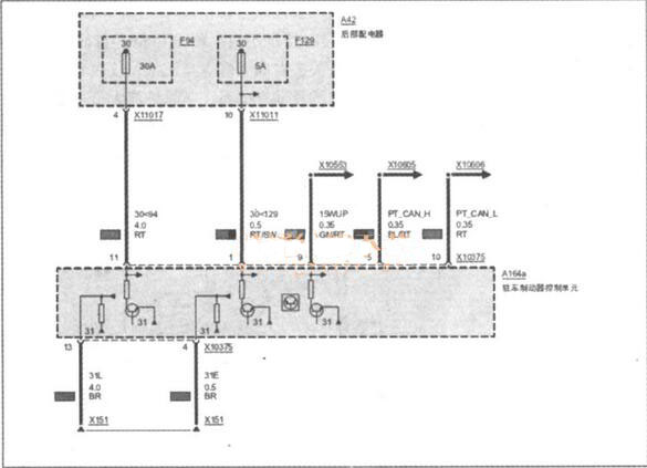
Check the cable connector of EMF,all work well without bent,corroded.Measure the power supply terminals X10375 pin11 and pin1,the voltage is 12V,it is normal,and measured the X10375 pin 13 and pin 4,both work well,it means the EMF control circuit is fine.Next, perform EMF function detection. No matter whether you press or release the EMF switch button, the function lighting flashes continuously.The EMF warning light on and gave the EMF error massage,When you press or release the EMF switch button, you can’t hear the sound of the EMF actuator action, indicating that the EMF has no action, so it is determined that the EMF itself is faulty.
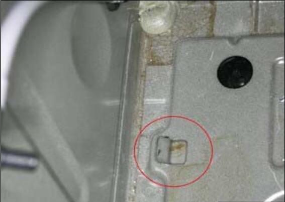
In order to find out the reason of EMF trouble,mechanic disassemble the EMF and found the negative terminal of the EMF actuator has been burned out.
Replace the EMF assembly, delete the fault storage, and troubleshoot.