Sunday, February 28, 2021

How to solve EMF Control Module Trouble on BMW E70 X5 2011 with BMW ICOM A2 A3 NEXT A+B+C?


BMW ICOM Software Version : V2020.05

ISTA – D: 4.22.32,with SDP Programming Database 4.22.32

ISTA – P: 3.67.1.006 with Engineer Programming,supports the programming of BMW motorcycles and electric vehicles

can program F/G/I/K chassis for car (through the ICOM, not other cable )

Vin: V2020.2.15


BMW ETK: 2020.1

BMW KSD: 2020.01  Multilanguage

BMW FSC Navigation Code Generator

BMWAiCoder for BMW Coding


BMW ICOM A2 +B+C NEXT V2020.05, With free Software:

  1. Get engineer version, INPA 5.00,winkfp 5.2.3,NCS 3.5.1, e-sys 3.30,data V67.0. get Chinese software DR.GINI B020
  2. get count code navigation tool software FSC operator code
  3. get one-clik hidden brush tool BMWAi V4.6
  4. Add DIS Software for Old cars, DISV57 and DISV44,diagnosis and programming for BMW virtual machines.


A BMW E70 X5 2011 with 4300km,the owner described that when starting after parking,the EMF warning light on,and parking brake function can not work correctly.


Mechanic staff released the parking brake mechanically,and then use ISID to diagnosed,got the below fault code:

5F12 DSC: Brake-pad wear, front axle, brake pads

5F10 DSC: Brake-pad wear, front axle, sensor

6DDC DSC: EMF: interface

600E EMF: Control module: internal fault (engine circuit)

6011 EMF: Control module: internal fault (engine circuit)

6031 EMF: Emergency release detected


The E70 is equipped with electro-mechanical parking brakes (EMF) in batches, which are used to prevent stationary vehicles from moving on their own.The parking brake is operated by the parking brake button in the center console. The parking brake button is located in the center console, behind the gear selection button (GWS).


The parking brake button is simulated in the hand brake operating logic:

Pull up the parking brake button: the parking brake is activated

Press the parking brake button downward: the parking brake will quit working


The dynamic stability control system (DSC) is the main control unit of the electro-mechanical parking brake (EMF).When the engine running or the vehicle on road: The parking brake hydraulically acts on the disc brakes on the front and rear axles via DSC.When the engine is off and the vehicle is stationary: The parking brake is applied to the drum brake of the rear axle by means of an electro-mechanical servo unit.The release action can be triggered by pressing the parking brake button,and the correspondingly activated brake system opens.When stationary, the parking brake can only be released by manipulating the foot brake, whether the engine is running or off.


EMF powered by rear distributor (2 bus terminals KI.30),it can be adjusted electromechanically through the transmission mechanism connected to the motor and flange.At this time, the pull wires act on an expansion lock that locks the rear drum brake. The force sensor provides an adjustment force signal to the EMF control unit. In order to ensure the required braking force, the adjustment force must be checked. A spring is integrated in the force sensor at the end of the wiring.The force sensor performs a displacement measurement when the spring is compressed, and this displacement measurement is based on the Hall effect.


When the EMF fails or is faulty, the EMF warning lamp and indicator light are on. When the EMF fails (for example, the fault code storage record) or when the power supply voltage is not high enough, a mechanical emergency unlock is provided,this emergency unlock makes it possible to manually release the servo unit.


Select the fault code “600E-EMF control unit: internal fault (engine circuit)” to execute the test plan. The system analyzes the fault frequency for 4 times. It is recommended to visually inspect the plug connection on the EMF control unit (curved leg, corrosion, and firm fixation) The circuit diagram checks whether the ground fault (pin 4, pin 13) and power supply (pin 1, pin 11) have the above-mentioned faults. As shown
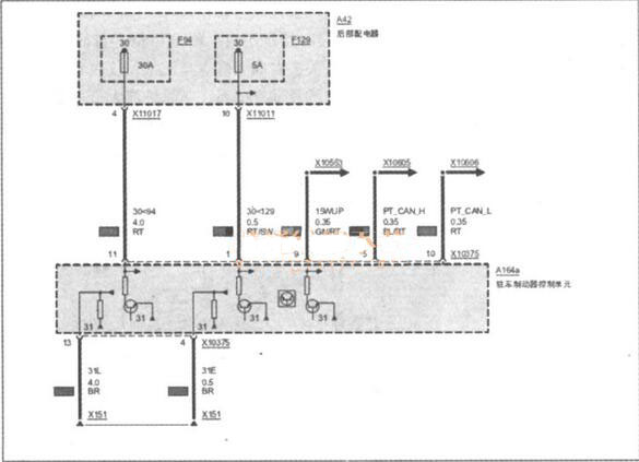
Check the cable connector of EMF,all work well without bent,corroded.Measure the power supply terminals X10375 pin11 and pin1,the voltage is 12V,it is normal,and measured the X10375 pin 13 and pin 4,both work well,it means the EMF control circuit is fine.Next, perform EMF function detection. No matter whether you press or release the EMF switch button, the function lighting flashes continuously.The EMF warning light on and gave the EMF error massage,When you press or release the EMF switch button, you can’t hear the sound of the EMF actuator action, indicating that the EMF has no action, so it is determined that the EMF itself is faulty.


In order to find out the reason of EMF trouble,mechanic disassemble the EMF and found the negative terminal of the EMF actuator has been burned out.


Replace the EMF assembly, delete the fault storage, and troubleshoot.

Tuesday, February 23, 2021

How to Solve High Battery Discharge Warning on BMW F01 F02 with BMW ICOM?

For BMW F01 F02,after the vehicle is started, a Check Control message “High Battery Discharge Warning” is displayed in the Central Information Display (CID).


Various power supply and power management faults are stored, including the following:

CAS – “930769 Deactivation of terminal 15: upper startability limit reached”

CAS – “93076A Deactivation of terminal 15: upper startability limit reached, but deactivation preventer or legal load/consumer active”

CAS – “93076B Deactivation of terminal 30B: upper startability limit reached”

CAS–“93076C Deactivation of terminal 30B: upper startability limit reached, but deactivation preventer or legal load/consumer active”

JBE– “8020E8 Reset or deactivation of terminal 30F”

DME–“213901 Power management: reduction or deactivation of individual electrical loads/consumers”


CAUSE

The battery has become heavily discharged or is faulty. The following reasons can contribute to a prematurely failing battery:

Unfavorable driving profile – excessive short trips

Excessive terminal 30B after run – normal coolant pump or electric fan operation

Extremely cold temperatures

Vehicle faults – closed circuit draw, sleep mode preventer or frequent wakeups


PROCEDURE

1.Perform energy diagnosis and follow the recommendations of the test plan

2.Test the battery:

a.For vehicles up to September 2010, use the BMW battery tester.

b.For vehicles after September 2010, use the advance onboard diagnostics with ISTA.

3.If the results of the battery tests indicate that the battery needs replacement, continue to the next step. If the results of the battery test state to recharge the battery, ensure that you are charging the battery sufficiently before testing. This can take from 1 to 6 hours, depending on the size and discharge state of the battery. As a rule of thumb, if the battery was heavily discharged quickly, it should be charged quickly. If the battery was discharged over a long period, it should be recharged slowly. Refer to the operating manual that came with your battery charger on proper settings.

4.Replace the originally equipped 90 AH AGM battery with a 105 AH AGM battery. Refer to ISTA Repair Manual “61 00 … Notes for disconnecting and connecting battery.”


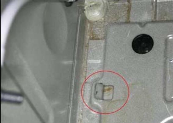
Important Note: Before mounting the battery in place, bend the metal tab down flush with the battery tray.

In some cases, a longer battery vent tube must also be installed in order to facilitate the larger battery.

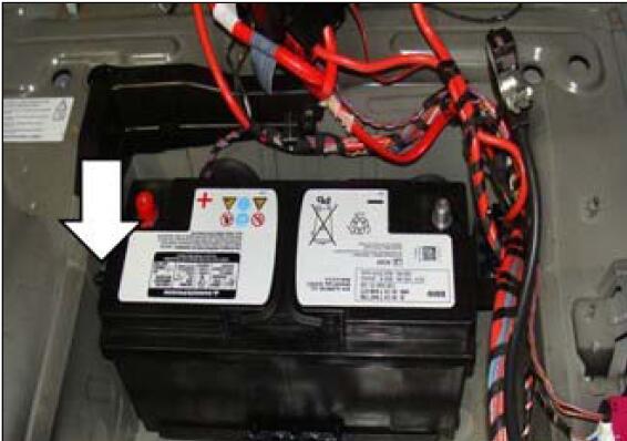
Before mounting the battery in place,make sure the battery vent hose is connected as indicated by the arrow.

The short end of the elbow should be connected to the battery to gain some extra clearance.

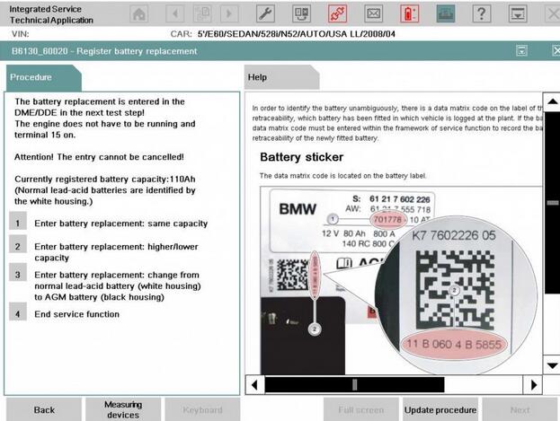
Record the matrix and supplier code from the label of the battery for entry in the next step.

The original battery hold-down clamp can be used with the new battery.

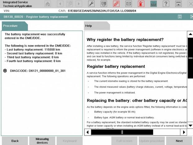
5.Register the new battery using ISTA. Select “Enter battery replacement:higher/lower capacity.”

6.Submit a PuMA case with the subject “B61 03 13 105 AH battery” to get a modified Vehicle Order (VO).

The modified VO will have A090 removed and A105 added.

7.Once the VO is downloaded from PuMA, start an ISTA/P programming session and import the new VO into the vehicle.

8.Select “Complete Coding” and program the entire vehicle with the current version of ISTA/P.

9.Note that ISTA/P will automatically reprogram and code all programmable control modules that do not have the latest software.

For information on programming and coding with BMW ICOM ISTA/P, refer to CenterNet / Aftersales Portal / Service /Workshop Technology / Vehicle Programming.

10.Check the functionality of the vehicle and make sure the “Battery Discharge” CC message is not displayed.


Important note: All subsequent battery replacements on these vehicles will require installation of the 105 AH AGM Battery.

Friday, September 7, 2018

Bmw Icom A2 interface

Topic:
I have recently bought the new BMW Diagnostic Tool Icom A2 interface with Isid 3.1, Ista/d 2.36 and Ista/p 2.49.2 software and i would like to ask if anyone knows if it’s possible to connect wireless to the car’s obd without the LAN cable since it support’s WLAN option or what else needed to make it possible? The Icom A2 interface is a clone.
Replied by shawnsheridan
I don’t think any of the A1 ICOM Clones had WLAN card inside, and I would be surprised if A2 ICOM Clone did. If it does, I am pretty sure you need a special Access Point connected to ISIS Server to use WLAN mode.
Replied by TroyE60
Thanks mate for your answer. Actually the ICOM A2 supports Wireless lan. As you can see from the below pic which I have already uploaded (Icom A2 connected in my car’s obd slot) with the system light green (turn on – operational) it has 4 lights. One for communication, one for wireless lan, on for LAN (RJ 45) and one for the operation named system. I was wondering if there is some kind of emulator or something to “trick” the interface so it thinks it is connected on an ISIS server even running from VMware.

How to convert HALOGEN to LCI HEADLIGHT with a ICOM cable


It’s a HALOGEN TO LCI HEADLIGHT Tutorial!!!!
Excuse my English I hope this help some of you guys!
In this site you will see the diagram for wiring!
Now after you know what your going to do with the wiring uninstall the frm and install frm2.
You will need NCS expert and Winkfp and inpa! and the icom cable obd to the computer! when you get the cable just read instruction and you ill be fine.. but just in case if your cable didnt bring the instruction here is how to program the cable make sure the computer read the cable if not download the driver after your pc read cable go to start on computer right click properties, device manager,then PORT click on it look for the cable then double click then a window will open lick on port setting (tap) click on advance at the bottom and make sure to set COM to COM1 and the latency to 1 it should be on 16 from default click ok and you are ready to go!
After you install all this software you need to open NCS expert to Change VO and VIN to yor frm2. And then program it!
OK now if you have AHL you need to add this VOs $522 and $524 to CAS and FRM and change production date that is going to be like this for example (#1205) you have to change it to at least #0307. and if you have just xenon add $522 and production date #0307. NOW question is how to do it.
open NCS expert on file tap load profile select expert mode F1,F3 select chassis e89 and select CAS now F2 (ENTER FA) select chassis again then enter vin# of the car
now a new window will open with a list of numbers.. is gonna say attribute ADD and OK at the bottom now we are going to add $522 and $524 and click in top of the first one that is the production date and hit the delete bottom on your keyboard and add the #0307 and click OK then F6 back then choose F4 choose CAS then F2 change job to FA_WRITE and F3 execute job and you are done!
Now you have to pass that information to “NFRM”
1.open NCS expert
2.File-Load profile
3.select EXPERMODE
4.press F1
5.press F3
6.select E89<for E90>
7.select CAS
8.F6 back
9.now you will be able to see your (FG) VIN # at top and (FA) VO
10.press F4<CHOOSE ECU>
11.select NFRM
12.after that select F2 chenge Job
13 choose FA_WRITE
14.F3 executive job wait a little bit and it will say courin beenet or coded ended something like that! now your VO are the same CAS and NFRM
NOW to change VIN
I did it the same way as CAS but instead of choose FA_WRITE i Choose FG_SCHREIBEN
1.open NCS expert
2.File-Load profile
3.select EXPERMODE
4.press F1
5.press F3
6.select E89<for E90>
7.select CAS
8.F6 back
9.now you will be able to see your (FG) VIN # at top and (FA) VO
10.press F4<CHOOSE ECU>
11.select NFRM
12.after that select F2 chenge Job FG_SCHREIBEN then F3 execute Job
now to make sure everything is good Go back to the main menu (or restart ncs-expert) and get the vehicle order from the “NFRM” module. Make sure NFRM returns YOUR VIN and YOUR VO. We want the VIN (FG) and VO (FA) to be the same in both CAS and NFRM. To do this same steps load profile expertmode F1,F3 select chassis and select “NFRM” NOT CAS!!! and it should be your VIN and VO the same as CAS.
Now to program NFRM you have to use Winkfp but first you need to know the part number of the NFRM using inpa that is gonna show on inpa FRM_70. go to inpa folder and look for inpaload select chassis and a window will open and select the first one functional jobs then f2 indet in there you will look for FRM_70 and copy the ZUB that is the part number IT should say for example (9204527) this is a example copy that number down and close inpa. now open Winkfp and choose confort mode F1 enter ZUSB put the number that you wrote down here and ill look for your frm automatically click ok then F4 Enter Vin put your car vin # click ok and then update ZUSB look for the one that gives you in the first step for ex(FRM2) then click on done! if it gives you an error 106 is because you dont have the cable plug in into the car! after that lick on F3 Prog. ZB UPdate and wait until is done and you are done!
Now to make sure BMW Diagnostic Software NFRM is default in NCS expert
load profile then go back to file and click edit file and click on FSW/PSW and uncheck the option “FSW/PSW manipulate with FSW_PSW.MAN” then click ok and choose profile info and on the name put whatever name that will remember you that thats the profile to code to factory any ecu using NCS expert then click ok and ok again that windows will close and click file save as and put the name that you choose.. Then F1, F3 choose chassis then CAS then F4 choose NFRM then F2 SG_codieren then F3 done!
Now to code with NCS expert you will need to create a FSW_PSW TRC file..
here is a video on Youtube but just in case if the video is not working ill write it down
To do this you have to Open NCS expert load profile expertmode
same F1,F3 select chassis select CAS F6 back choose ecu F4 NFRM and change job F2 CODIERDATEN_LESEN then f3 execute job now dont close ncs expert and go to ncs expert folder then to work folder and you will see that there is a FSW_PSW trc file open the file change what ever you need to change and after you change everything save the file.. go to file and click save as and write FSW_PSW.MAN now go back to NCS expert and Click on file edit file and go to FSW_PSW click on it and make sure to check the option FSW_PSW manipulate with FSW_PSW.MAN click ok then choose ECU F4 select the Ecu that you choose to read with CODIERDATEN_LESEN earlier and now change to to SG_codieren and F3 execute job and You are DONE coding!
THANK YOU FOR READING I HOPE THIS WILL HELP SOMEONE I SPENT 2 WEEK TO LEARN ALL THIS AND NOW I WANT TO SHOW IT TO YOU GUYS!

How to do BMW coding with ISTA on MacBook Pro

Here are the details of my setup of MacBook Pro with VW Fusion – Windows 10 or Bootcamp, both working for BMW coding with ICOM software.
Hardware: 2015 Retina Macbook Pro 16GB RAM, 512GB SSD
Software: VMWare Fusion 10
VM Specs:
Windows 10 64Bit
4GB RAM
Thinly provisioned 200GB VM. (Thin means it only takes the space it is using but Windows thinks it is 200GB total.)
Software working on VM:
BMW Standard Tools 2.12 (NCSexpert, WinFKP, INPA, etc)
ISTA-D (Dealership Diagnostic Software, I did not install ISTA-P due to space concerns)
E-Sys (For newer Fxx/Gxx/Ix cars)
I back up my VM on an external hard drive and I take snap shots of the VM in case upgrades to the software fails and breaks.
I am very happy with this setup.
Another option instead of VM fusion is to bootcamp the mac. That’s what I’ve done also. It partitions the hard drive into separate drives, allowing you to boot the Mac up into windows natively. Then used bimmergeeks.com software packages. It’s very clear and easy to understand. It’s also been condensed some and has the most recent updates in place….
BootCamp
Pros:
Free + windows 10 license
All system resources are utilized by Windows only.
Acts like a windows machine
Cons:
Requires permanent space allocated to BootCamp
Requires rebooting if you ever want to go back to Mac
Unable to write into MacOS side of things without 3rd party drivers
VM
Pros:
Snapshots
Space allocated is only like a file, so free space is still utilized by Mac
No need to restart to get into Windows for something.
Cons:
Not free, and annual upgrades start to cost a lot
Shares resources with MacOS which can be limited if the Mac doesn’t have enough RAM, CPUs etc.
A little more complicated in initial setup sometimes.
Both have its merits and I ultimately like BMW ICOM A2 when the mac has enough resources to run it.

www.obd2tool.com

BMW Battery Registration with Rheingold ISTA

Topic: focus on why register the BMW battery replacement, BMW Battery Registration with Rheingold ISTA procedure.
BMW Battery Registration
BMWs need to know when you replace the battery, battery capacity and battery type must be registered! YOU DO NEED TO REGISTER battery replacements on BMWs with an IBS (Intelligent Battery Sensor).
Why register the battery replacement?
After installing a new battery, the service function ‘Register battery replacement’ must be run. The registration of the battery replacement is required to inform the power management (BMW Diagnostic Scanner in engine electronics and intelligent battery sensor) that a new battery was installed in the vehicle. If the battery replacement is not registered, the power management will not function properly and can lead to functions being limited by individual electrical consumers being switched off or having their power consumption reduced. Power management will charge the new battery as if it’s the old worn out battery, causing premature failure of the replacement battery.
Important! If the new battery is not registered, incorrect readings may appear in the display of the on-board computer due to old data in the power management system (check control message ”Recharge battery” appears even though the battery is new).
12-1
A service function informs the power management in the Digital Engine Electronics (DME) or the Digital Diesel Electronics (DDE) of a battery replacement. The following operations are performed:
-The current mileage reading is stored for the battery replacement.
-The stored measured values (battery charge statuses, current, voltage, temperature, etc.) are deleted.
-The power management is initialized.
12-2
Available registration options:
Replacing battery with exact same type – (Simple registration)
Replacing battery with same type but different capacity – (Registration/Conversion)
Replacing battery with different type – (Programming/Conversion/Registration)
Updating software of complete battery management system
Changes to the charging profile also affects how the Start/Stop system works for vehicles with EfficientDynamics
Car 1:
You’re renewing the battery with identical replacement. You register replacement to let the car know that the battery is new and the charging profile is adjusted accordingly. If you don’t the vehicle will charge for an old battery and cause premature failure.
Car 2:
You fit an AGM in place of a Standard LA battery (or vice versa). If you don’t register the replacement then it will toast the new battery for similar reasons to Car 1 but even worse as the charging profile will be for the incorrect type battery and cause even faster battery failure. In this case you MUST use a ‘conversion’ to change the battery type. Then, register a replacement.
BMW Register battery replacement
12-3
Notice! Determination of state of charge after a battery replacement
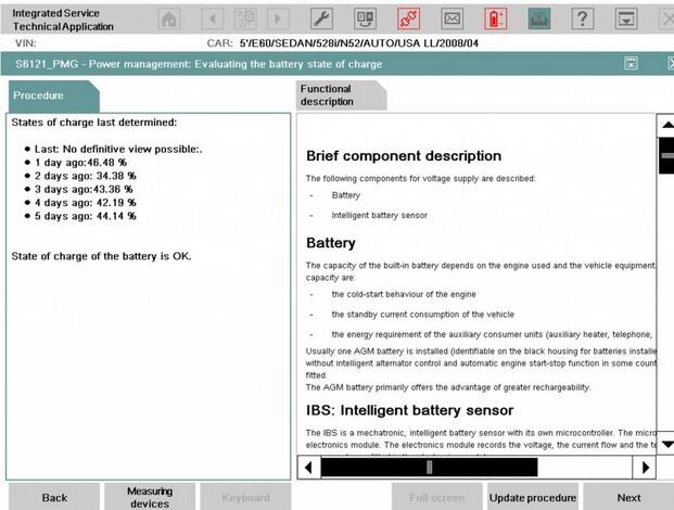
After a battery replacement, the vehicle must be left standing for at least 3 hours with its new battery. It is not possible to establish with any reliability the state of charge of the new battery until that time. Possible Check Control messages about total discharge of the battery are then no longer displayed.
BMW battery state of charge
12-4
Notes for disconnecting and connecting battery
The scope of application of some systems may be restricted after a power supply interruption. Likewise, individual settings may be lost.
Settings or activations must be carried out, depending on the equipment specification. For example:
.Vehicles with automatic engine start‐stop function (MSA): MSA function is active only after learning period (vehicle must not be woken for a period of approx. 6 hours
. E46 Perform (four-wheel drive) / E53 / E83: steering angle sensor adjustment
. If necessary, activate slide/tilt sunroof
. If necessary, activate power windows
.If necessary, activate mirror with compass
Only E60, E61, E63, E64, E70, E71, E90, E91, E92, E93: mount steering angle
Skipping the battery registration process can dramatically shorten the life of a battery in these vehicles, be it an AGM or a conventional battery. Several issues can cause premature battery failure, see post on Energy Diagnosis, but on a late model BMW, skipping battery registration can be one of them.

http://cheapobd2.com/2018/09/05/bmw-battery-registration-with-rheingold-ista/

How to Diagnose BMW MSD80 DME with INPA software

Purpose: To see the BMW Diagnostic Tool options is working or not, on 525i with an engine N53.
Diagnostic tool: BMW ICOM A2/ICOM Next with ISTA
Important: compare possibilities of ISTA D with INPA.
Vehicle information:
Car: BMW 5 series E60 sedan 525i
Year: 2007/09
Engine: N53
EURO
Manual
DME: MSD80
The test:
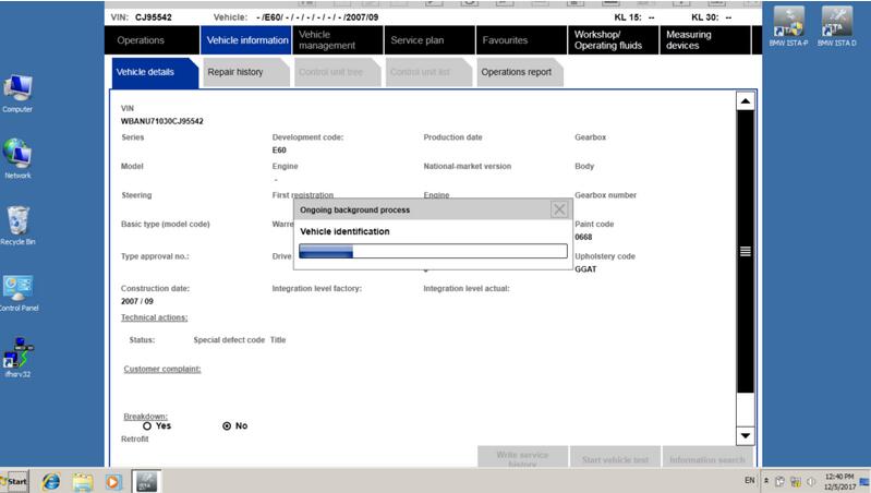
ISTA-D is identifying the vehicle
11-1
and reading FASTA information
11-2
the basic menu is available.
Service procedures and data, intended for the engine, are available in two groups:
a) basic menu: Vehicle management/Service function/Powertrain/Engine Electronics
b) Call up ECU functions menu of the engine management unit
In the basic menu you can choose:
a) viewing data correction of cylinder Rough run and Stoichiometric mixture;
b) coding the injector data;
c) coding new NOx catalytic converter and NOx sensor, activate Desulphation session;
d) delete adaptations;
e) perform misfire/Rough run test for cold engine and view the “opinion” of DME, which engine has problems with smooth running.
In DME Call up menu you can choose:
a) view live data;
b) perform activation tests for several knots.
Now, start the review with DME Call up menu.
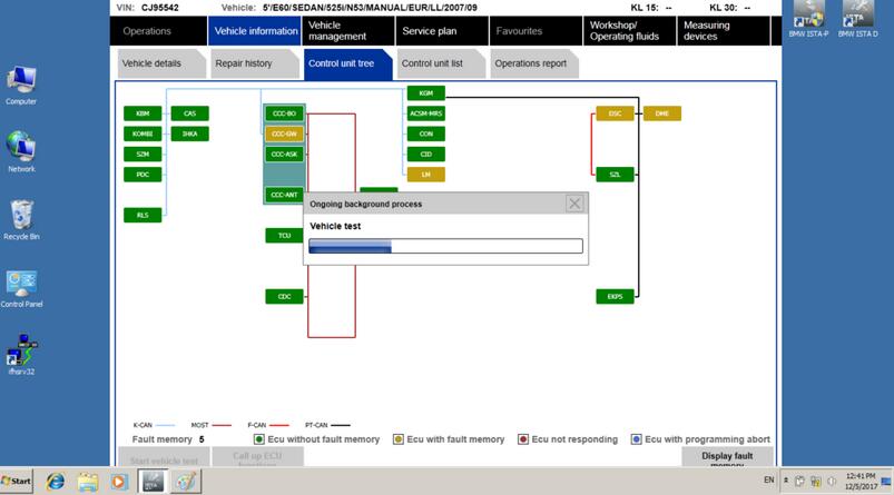
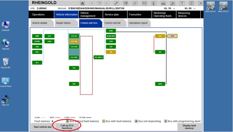
To enter it, click with Mouse on DME icon on the “tree” of units and press the button “Call up ECU function”.
11-3
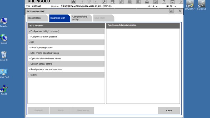
Call up menu contains three basic choices:
a) identification: basic data of ECU unit;
b) diagnosis scan: live data;
c) component triggering: activation/test blocks.
11-4
“Identification” menu is very clear, so we move to diagnosis scan menu – content of it is seen in the image above.
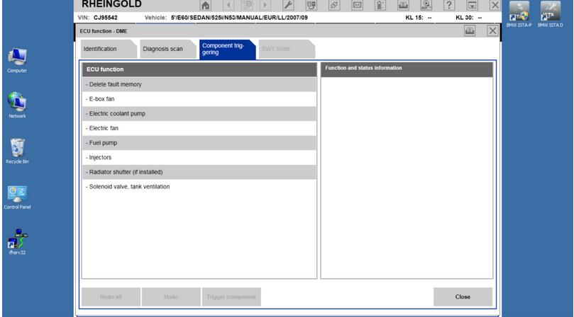
The content of Component triggering submenu :
11-5
Unfortunately, the amount of test blocks is tiny. As can be seen, it’s possible to test the pressure of the low-pressure pump, in the injectors menu: switch off any of cylinders, switch on the water pump and electric fan.
Blocks of engine performance modes, Lambda probes, generator, VANOS, EGR and many other important knots are not available.
Diagnosis scan submenu.
a) fuel pressure (high pressure);
b) fuel pressure (low pressure);
c) idle;
allows to view exact values of the parameter and are not very interesting. Only remark (it refers to all analog/live data values, displayed by ISTA):
a) data representation is in small size, it’s hard to see the data, for example, during the driving session;
b) main part (with rare exceptions) of data have no reference value, no min/max limits displayed; no explanation for specific data;
c) bar type indicators are not used – they would ease the viewing of variables.

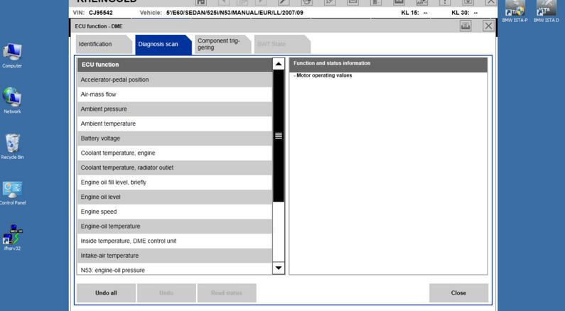
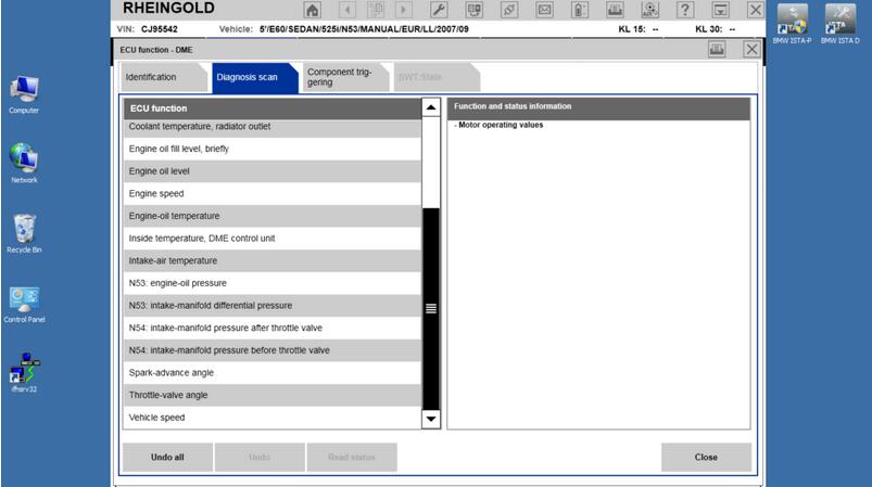
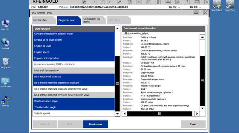
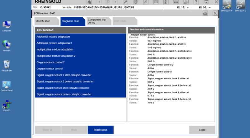
The content of Diagnosis scan submenu, choosing ”Motor operating values”:
11-6
11-7
To read the required parameters, they have to be chosen (it/they will color in blue) and press the button ” Read status”.
Example, how does a viewing of live data look’s, using ISTA D:
11-8
Unfortunately, data are opaque – there is no visible separation, no ref/min/max limits, no bar indicators.
Several disadvantages of menu:
a) oil pressure – no required oil pressure displayed;
b) no PWM for keeping up the pressure is displayed;
c) data of detected pressure are displayed with an offset of -1000hPa.
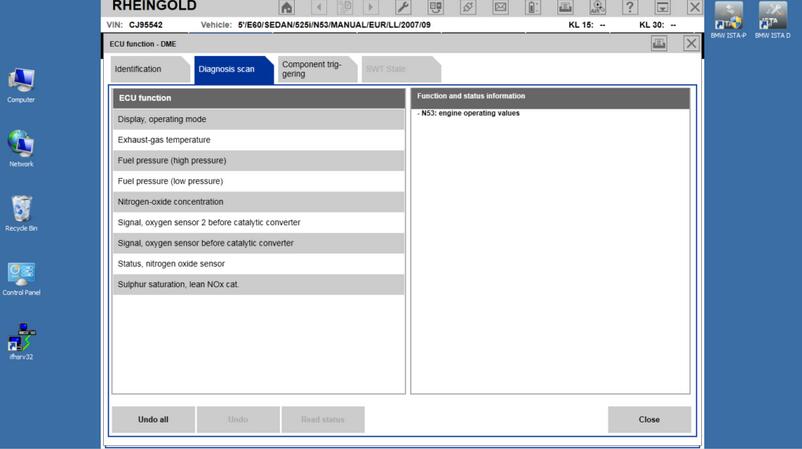
The content of submenu, choosing operating values of the N53 series engine:
11-9
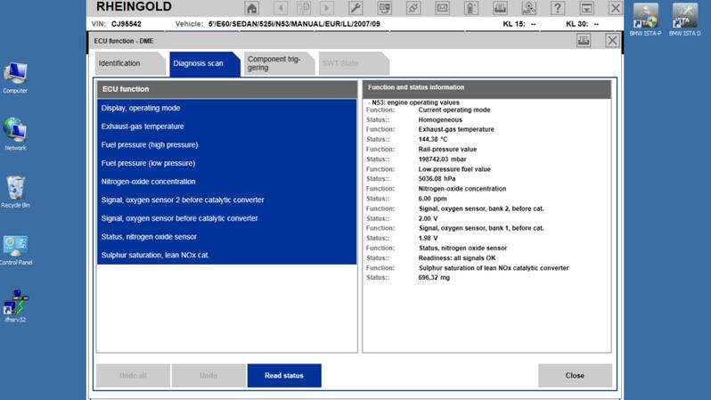
Live data of these parameters:
11-10
This submenu has “several” disadvantages:
a) the engine performance mode is displayed, but no Lambda values, with which the engine works, can be seen;
b) no possibility to overlook data during the desulphation process;
c) no PWM both for the low-pressure and high-pressure system can be seen – no information of system’s ability to hold the pressure;
d) no Offset values for NOx sensor data are visible, no reported Lambda values (wide-band and narrow-band).
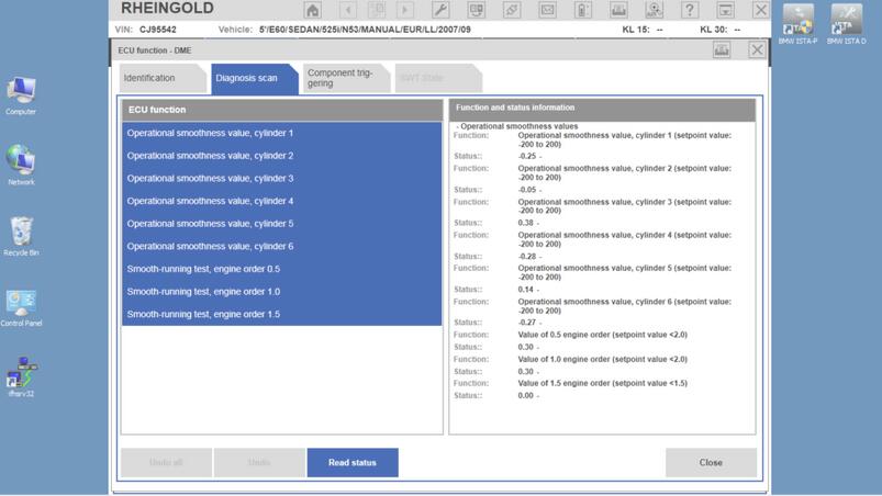
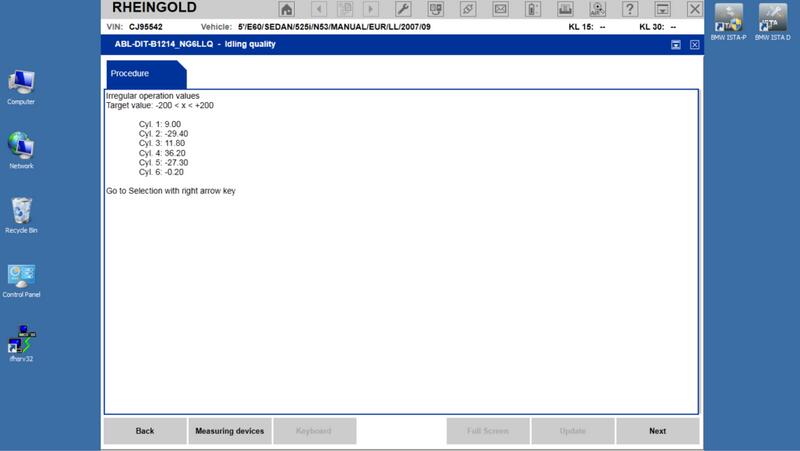
Data of “Operational smoothness values” submenu:
11-11
In this menu, Rough run value min/max values ( +/-200) are displayed. According to the software release, in case of the normal engine performance, the values fluctuate in limits of +/-0.2, for some releases – only within limits of 0.02. It means, 0.1 or even 0,01% of max displayed! Conclusion – these indicated values are just confusing the user!
It’s not even worth to mention, that math, which would describe the coefficient ”engine order 0.5/1.0/1.5”, is not even present.
Content of ”Oxygen-sensor control” submenu:
11-12
This submenu has “several” disadvantages:
a) multiplicative adaptations are not displayed at all;
b) Lambda value for wide-band probes is not calculated/displayed; no description, how to interpret “voltage” indications;
c) PWM of probe heating is not displayed, from the status description it’s not clear, is the probe being heated or is already heated;
d) no Nernst resistance for probes is displayed, chemical activity of probes cannot be seen; no manual control of probe heating is possible;
e) the engine performance mode (requested/confirmed) is not displayed;
f) required Lambda values and their conformity to measured are not displayed.
No data available about:
a) injectors: learnbits;
b) injectors: real time values (opening time; multiplicative adaptations; voltage; energy, etc);
c) injectors: mechanical and chemical tests/results.
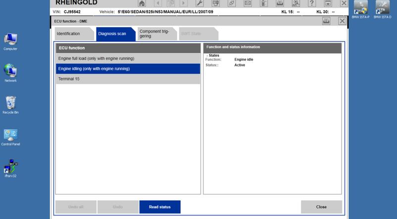
Submenu ”States” contains some of the status bits:
11-13
Unfortunately here the viewing of engine Live data ends. As you can see, the amount of displayed data is many times less than with INPA, and displayed data cannot be viewed easily.
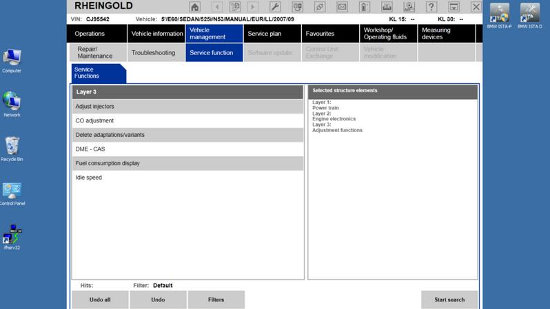
Vehicle management/Service function/Powertrain/Engine electronics menu,
11-14
Idle speed/Idling quality submenu:
11-15
Rough running values:
11-16
Rough run values for correctly performing engine display lasting disbalance, therefore it’s not clear, what are these data. Possibly – applied Offset type corrections for each injector to reach smooth performance.
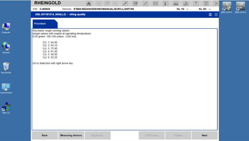
Stochastic irregular operation data:
11-17
Also regarding these data – no information. In ideal scenario – all values are targeting 0? Or, most probably: all values are targeting 50; increased value – decreased mechanical efficiency.
We can only pay our condolences to a specialist of the dealer center, who has to work with such “data”.
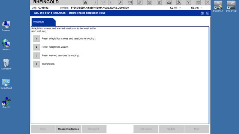
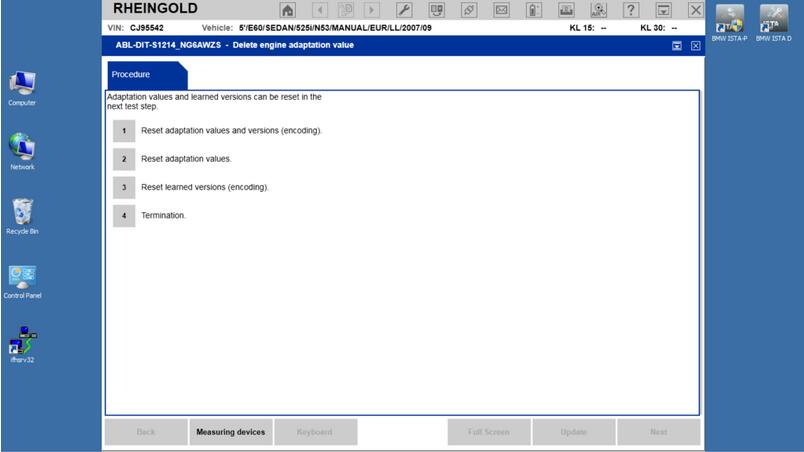
Delete adaptations submenu:
11-18
Unfortunately – no information, which menu deletes which group of adaptations.
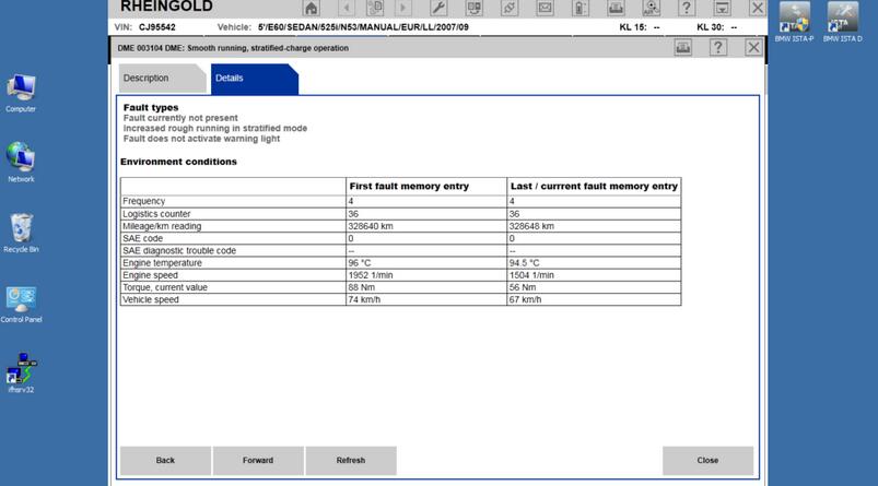
Also, information regarding stored error messages is more than modest:
11-19
For example, in the existing situation, INPA freeze-frame will additionally display:
a) engine performance mode (Homogeneous/Homogeneous lean/Stratified charge);
b) engine status (work or heating up);
c) offset, multiplicative adaptation and integrator values, etc.
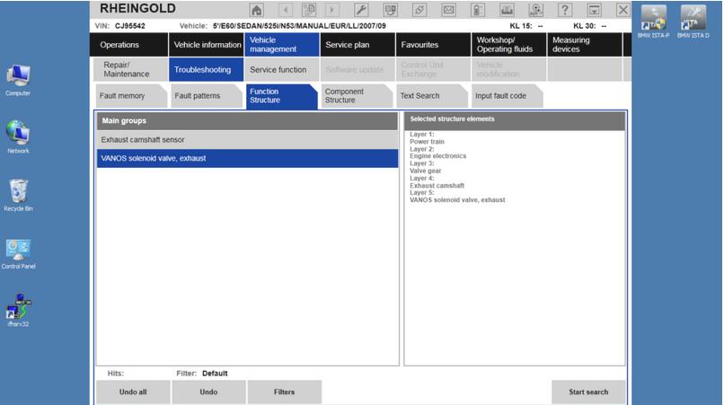
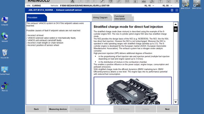
Data for separate knots can be seen into appropriate functionality blocks, as an example, we will view test block of VANOS:
11-20
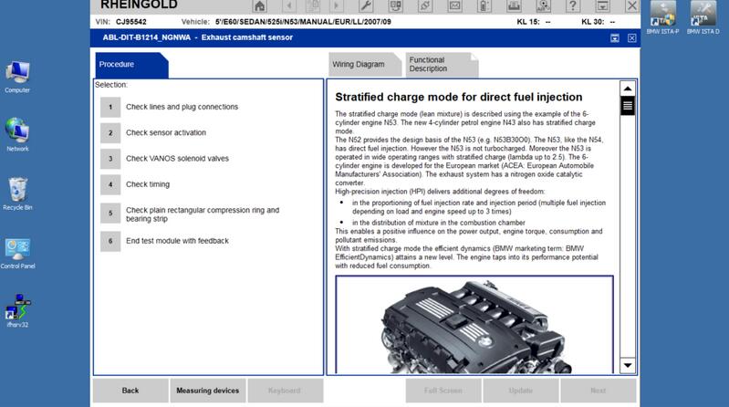
After choosing this test module, the menu opens:
11-21
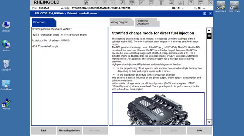
The detected position of VANOS can be seen:
11-22
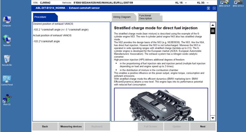
It is possible to perform test block, which tests the ability of VANOS knot to maintain the required position in one, fixed position:
11-23
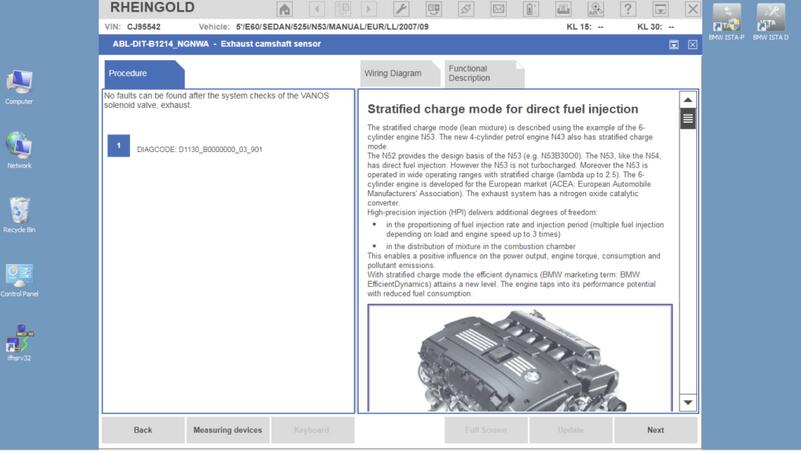
After performing such tests, the diagnostics specialist has to take the decision by himself, does the VANOS performs correctly – ISTA displays following menu of suggestions:
11-24
11-25
As you can see, this menu doesn’t give exact answers.
Additionally, there are no possibilities to choose the position of camshaft manually, evaluate the PWM of the valve, it’s jittering.
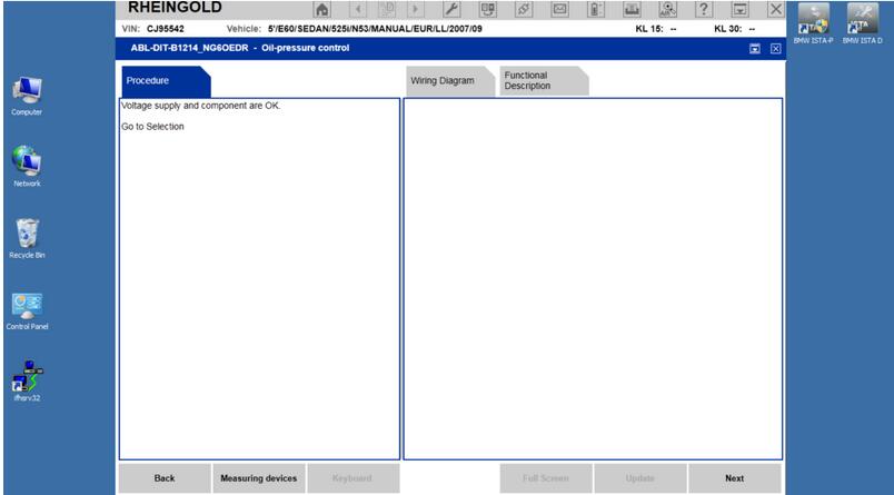
The situation with, for example, checking the oil pressure is even sadder. There is no possibility to compare the inquired and measured oil pressure, no possibility to evaluate the PWM of oil valve. No test block, which could be started. Only testing option, offered by ISTA: evaluation of PWM of the valve with an oscilloscope. And, if rectangular impulses are observed, ISTA reports, that everything is in working condition!
11-26
Everything is in order, not taking into the account the PWM value, not taking into account it’s jittering? Impressive!
It is regrettable, that the dealer specialists are forced to work with such weak diagnostic tool. INPA options for MSD80 diagnostics are incomparably wider, but, for unknown reasons, INPA is banned for using in dealer service centers.
http://forobd2tool.com/blog/2018/09/05/how-to-diagnose-bmw-msd80-dme-with-inpa-software/